


Abstract
Due to the lack of knowledge about parasacral artery perforators, flaps from this region cannot be used with complete confidence in their security and effectiveness. Knowledge of the clusters and perforasome of these perforators could help in the design of more reliable flaps and extend the range of applications.
This study aimed to identify the location, number, and density of perforators, and to subsequently analyze the perfusion flow and linking vessel distribution.
Five fresh cadavers were harvested and dissected. For the mapping, after injecting lateral sacral arteries with colored latex, perforators with a diameter of >0.5 cm were examined in 5 sacral regions. All data were collected on the suprafascial plane, with an orthonormal coordinate system placed on iliac crests and median lines. For perforasome analysis, 5 perforators and 3 three sacral flaps were injected with radiopaque dye. A dynamic (4-dimensional) computed tomographic angiography completed the analysis.
A mean [standard deviation] of 8.4 [1.36] perforators per corpse, with a mean diameter of 0.72 [0.14] mm, were identified. There was a higher density of parasacral perforators close to the median line and 7.6 cm above the iliac crests. This pattern was not a random distribution (P < 0.05). The perfusion area was preferentially in the superior gluteal region. Perfusion flow was permitted by the dominant direct-linking vessels towards adjacent lumbar perforators, oriented diagonally upward and outward to the midline.
Parasacral perforator flaps appear to be a useful procedure in reconstruction and in aesthetic surgery, especially in gluteal augmentation. Their reliability depends on sound anatomic knowledge, with accurate preoperative perforator mapping.
See the Commentary on this article .
There is increasing use of perforator-based propeller flaps to cover defects of the lower back close to the midline.1-3 However, there are no vascular anatomy studies on perforators specifically concerning parasacral arteries available in the literature. Some authors even consider that parasacral artery perforators (PSAPs) and superior gluteal artery perforators (SGAPs) are a single anatomic entity.
Managing skin defects in the sacral area with propeller perforator flaps is simpler than utilizing traditional flaps.4,5 The technique has many advantages, including the “like-with-like” principle and lower morbidity of the donor site. However, a lack of knowledge prevents the best use being made of this procedure. Perforasome and cluster studies of flaps could change the indications for modeling larger skin paddles but be just as reliable for flap reconstruction.6
Few studies have been conducted on sacral artery–based perforator flaps.2 Anatomically, 2 lateral sacral arteries (LSAs) and a median sacral artery (MSA) are described, located in the retrorectal space.7 The MSA is a single artery that descends the sacrum and coccyx and supplies 4 transverse branches on each side. The LSAs have 2 branches: 1 superior and 1 inferior. The superior branch, which is the smallest, gives rise to the first medial branch. The inferior LSA, which is larger, successfully gives rise to the second, third, and fourth medial branches that lead to the corresponding foramina.
Each medial branch anastomoses with a transverse branch of the MSA before entering the anterior sacral foramina. These medial branches escape via the posterior foramina, perforates thick lumbar muscle, and vascularizes the skin on the dorsal surface. These artery perforators are called PSAPs8,9 and are illustrated in Figure 1.
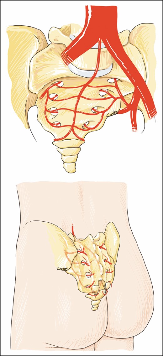
Parasacral artery perforator pathway: anterior and posterior view.
The objective of this study was to map the PSAPs by determining their location, number, and density. The perforasome of parasacral perforators was then analyzed by computed tomographic angiography. In addition, we illustrated the use of these perforators in buttock enhancement.
METHODS
Perforator Mapping
From May 2018 to September 2018, the sacral regions of 5 fresh cadavers (3 females and 2 males) were dissected after selective injection of colored latex into the LSAs, which were dissected via a median laparotomy incision. Before injection, the sacral region was warmed and elevated to avoid direct pressure. The cadavers were then cooled in the prone position for 24 hours.
The area examined was limited superiorly by the iliac crests, inferiorly by the coccyx, and laterally by the trochanter. All the perforators identified in the sacral area were considered PSAPs. These perforators emerged from the sacral foramina or flush with the bony rim of the sacrum. They were different from the SGAPs, which emerged more laterally within the gluteus maximus muscle.
Only the perforators with colored latex with a diameter ≥0.5 mm were selected as PSAPs and analyzed on the suprafascial plane. The number, diameter, location, distribution density, and trajectory were analyzed.
To map the perforators, we used a transparent grid sheet with a centimetric orthonormal coordinate system. The y axis passes through the midline, and the x axis joins the iliac crests. The horizontal axis was negative on the left and positive on the right (Figure 2). A point cloud and a heat map were used to identify the highest-density zone. To establish this heat map, we used R 3.6.2 software (R Foundation for Statistical Computing, Vienna, Austria). The high-density areas were defined as areas with a density of up to 0.6 perforators/cm2, superior to the overall average density.

A transparent grid sheet placed over the examined region for a 75-year-old female patient.
Perforasome Assessment
In the anatomy laboratory, the first step was to inject the perforators with warm diluted methylene blue under a controlled pressure of 130 mmHg. The injection was stopped when no more dye diffusion was noted. Through this feasibility study, the volume needed for the tomography stage was determined.
After the vascular network was saturated and the vascular leaks clipped, a blue area appeared. A total of 4 mL of methylene blue was injected in the perforators. This volume was used as a reference for the 3-dimensional (3D) computed tomographic angiographies.
Three sacral regions, harvested on a suprafascial plane, were then brought to the scanner room: 5 PSAPs with a diameter >0.5 mm were washed with a warm saline solution and injected with lipiodol, milliliter by milliliter, until the reference volume was reached under controlled pressure. Leaks were coagulated with bipolar forceps. Simultaneously, several tomographic images (Aquilon ONE GENESIS Edition; Canon Medical Systems Corporation, Otawara, Tochigi, Japan) were acquired. We obtained dynamic images (4D) and analyzed these with TeraRecon (Foster City, CA). This allowed us to analyze the perfusion flow and distribution of the linking vessels. Finally, injected flaps were radiographed. For flaps no. 1 and no. 2, 1 right and 1 left PSAP were injected, first the right one and then the left one. For flap no. 3, only 1 PSAP on the right side was injected.
Statistical Analyses
We divided the iliolumbosacral region where the perforators were identified into 6 equal quadrants, designated A to F (A, left lumbosacral quadrant; B, right lumbosacral quadrant; C, left midsacral quadrant; D, right midsacral quadrant; E, left inferior sacral quadrant; and F, right inferior sacral quadrant). This region was divided by taking the medial line as a reference and then dividing the region into 6 zones of 5 cm × 6 cm which allowed the inclusion of all the perforators identified in our anatomic dissections.
All perforators of the 5 dissected cadavers were indicated on a graph of the iliolumbosacral region according to their respective quadrants. A statistical analysis was performed to evaluate whether there was a significant difference in the number of perforators in some quadrants compared with others. Variables were expressed as means [standard deviation]. All statistical analyses were performed with StatiS (GraphPad Software, Toulouse, France). Values were expressed as percentages, and significance was set at P < 0.05; a Z-test was used to compare the percentage obtained with the theoretical value.
RESULTS
Perforator Mapping
A total of 42 PSAPs were identified on the subfascial plane of 5 cadavers, ie, a mean of 8.4 [1.36] perforators per sacral region, with a slight predominance on the left: on average 5 [1.26] on the left and 3.4 [1.02] on the right (Tables 1, 2). We found that 35 of the 42 PSAPs were located in front of the sacrum. The mean diameter of these PSAPs was 0.72 [0.14] mm.
Mapping Results for the Overall Sacral Region
| Cadaver | Overall sacral region | |||
|---|---|---|---|---|
| Number of perforators | Mean coordinates of perforators, cm [SD] | Mean caliber, mm [SD] | ||
| x axis | y axis | |||
| 1 | 8 | 0.2 [2.09] | 7.4 [2.34] | 0.64 [0.14] |
| 2 | 9 | –0.3 [2.91] | 9.7 [2.67] | 0.82 [0.09] |
| 3 | 10 | 0.2 [3.03] | 6.4 [2.74] | 0.73 [0.17] |
| 4 | 6 | 0.8 [2.73] | 6.2 [1.43] | 0.71 [0.07] |
| 5 | 9 | 0.9 [1.98] | 8.2 [2.77] | 0.67 [0.08] |
| Total | 42 | –0.3 [2.59] | 7.6 [2.90] | 0.72 [0.14] |
SD, standard deviation.
Mapping Results for Left and Right Sacral Side
| Cadaver | Number of perforators | Mean coordinates of perforators, cm [SD] | Mean caliber, mm [SD] | |
|---|---|---|---|---|
| x axis | y axis | |||
| Left side | ||||
| 1 | 5 | 1.1 [1.08] | 6.8 [2.92] | 0.59 [0.07] |
| 2 | 5 | –2.8 [0.76] | 9.4 [2.70] | 0.83 [0.11] |
| 3 | 5 | –2.2 [1.60] | 7.2 [3.25] | 0.72 [0.21] |
| 4 | 3 | –3 [2.50] | 6.5 [1.3] | 0.71 [0.07] |
| 5 | 7 | –1.8 [1.18] | 7.8 [3.79] | 0.68 [0.09] |
| Total | 25 | –2.1 [1.40] | 7.5 [3.05] | 0.70 [0.14] |
| Right side | ||||
| 1 | 3 | 2.5 [1.73] | 8.3 [1.60] | 0.73 [0.23] |
| 2 | 4 | 2.9 [0.85] | 10 [3.37] | 0.80 [0.06] |
| 3 | 5 | 2.7 [2.30] | 5.7 [2.61] | 0.75 [0.17] |
| 4 | 3 | 1.3 [1.44] | 5.8 [2.02] | 0.70 [0.10] |
| 5 | 2 | 2 [2.12] | 9.5 [0.71] | 0.61 [0.08] |
| Total | 17 | 2.4 [1.59] | 7.8 [2.66] | 0.73 [0.12] |
SD, standard deviation.
For the overall sacral region, the mean coordinates of the PSAPs were: x = 0.3 [2.59] cm and y = 7.6 [2.90] cm. On the right sacral region: x = 2.4 [1.59] cm and y = 7.8 [2.66] cm; and on the left sacral region: x = –2.1 [1.40], y = 7.5 (2.05) cm.
The coordinates and average of all perforators are represented by a point cloud on an orthonormal coordinate system over the 30 cm × 15 cm pelvis of a virtual subject. The size point is proportionate to the diameter of the perforators (Figure 3). A PSAP distribution density could be established from these coordinates, showing “hot” areas in red, where the probability of finding PSAPs is higher. In this area of interest, equal to 450 cm2 (30 cm × 15 cm), the average density of perforators was 0.1/cm2 (42/450 cm2). In contrast, for the densest area, ranging from orange to red, equal to 16.7 cm2, the PSAP density was 0.6/cm2 (10/16.7 cm2) (Figure 4).
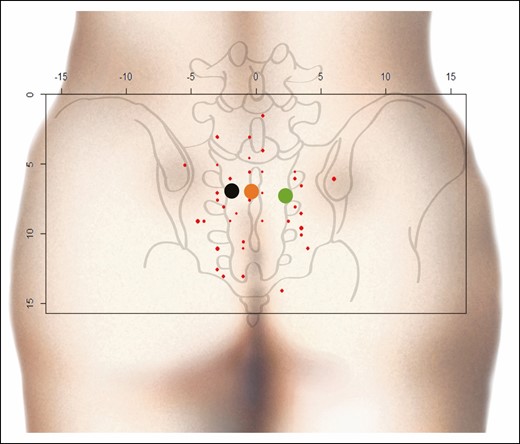
Point cloud. Red points, PSAP coordinates; black point, mean coordinates of the PSAP on the left side; green point, mean coordinates of PSAP on the right side; orange point: mean coordinates of all PSAPs. x and y axes in centimeters. PSAP, parasacral artery perforator.
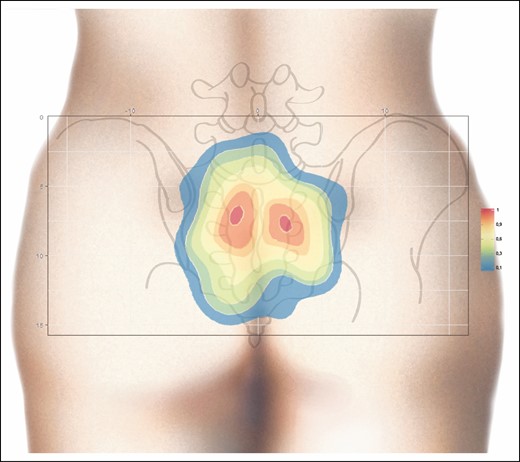
Heat map generated from the contour plot analysis for PSAP density. Two regions with a higher PSAP density (orange-red) are clearly shown. Right, scale with PSAP per cm2. PSAP, parasacral artery perforator.
The course of the PSAP was also examined in the 5 fresh cadavers used for mapping. At least 1 perforator always emerged from each posterior foramen. At this level, their caliber was systematically greater than 1.2 mm. After their foraminal emergence, perforators followed a sinuous course through the lumbosacral muscle. They then perforated the muscle fascia to enter the hypodermic plane directly and vertically (Figure 5). We also identified pericoccygeal perforators with a diameter of >0.5 mm, arising from the medial sacral artery and linked by anastomosis with the LSA. However, we did not consider them as PSAPs and they were therefore excluded from our data.
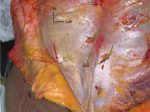
Dissection of PSAPs on a suprafascial plane for a 69-year-old female patient. Red arrow, PSAP with a vertical course; green arrows, other PSAPs clipped for location. PSAP, parasacral artery perforator.
Perforasome Assessment
In the anatomy laboratory, after vascular network saturation, a blue area appeared on the side of the injection and extended upwards and outwards, showing cutaneous perfusion of the upper gluteal region (Figure 6). Regarding the 3D computed tomographic angiography analysis, the main flow direction was preferentially oriented perpendicularly to the median line and diagonally upwards and outwards, ie, towards the iliac crests and the adjacent lumbar perforators which exhibited contrast medium regurgitation and leaks, showing a greater flow to this perforator network. This was noted in 4 out of 5 cases. In 1 case, the flow was directed only perpendicularly to the median line.
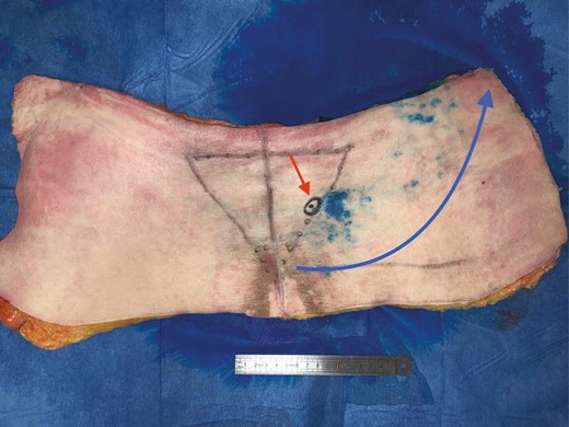
Study of the cutaneous vascularization of parasacral artery perforators after injection with methylene blue for an 80-year-old male patient. Red arrow, location of the catheterized perforator; blue arrow, flow orientation.
Finally, there was always a diffusion of contrast dye to the contralateral side, crossing the midline (Figures 7, 8 and Supplemental Figure 1, available online at www.aestheticsurgeryjournal.com). After network saturation, a final X-ray of the 5 samples was performed. The length of perforasomes reached 14 to 16 cm from the injected PSAP and extending laterally (Figure 9).
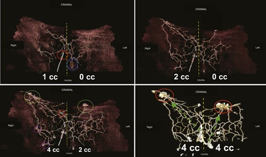
Three-dimensional computed tomographic angiography analysis. Top-left image: flap no. 1, right PSAP = 1 mL, left PSAP = 0 mL. Yellow dashed line, midline; blue circle, left PSAP; red circle, right PSAP. Top-right image: flap no. 1, right PSAP = 2 mL, left PSAP = 0 mL. Yellow dashed lines, midline. Contrast medium diffusion is visualized crossing the midline to the contralateral side. Bottom-left image: flap no. 1, right PSAP = 4 mL, left PSAP = 2 mL. On the right, the network is overloaded, whereas on the left, the product is progressing. The perforasome of the injected PSAPs supply adjacent perforasomes. Green circles, lumbar perforators; purple circles, upper gluteal perforators; red circles, other PSAPs. Bottom-right image: flap no. 1, right PSAP = 4 mL, left PSAP = 4 mL. Both networks are overloaded under controlled pressure. The red circle shows leaks of contrast medium. The green arrows are the direction of flow preferentially directed upwards and outwards (dominant linking vessels). PSAP, parasacral artery perforator.
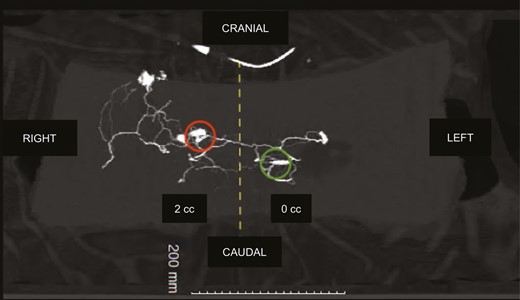
Three-dimensional computed tomographic angiography: flap no. 2, right PSAP = 2 mL, left PSAP = 0 mL. Same findings for flap no. 1: preferential flow towards the iliac crests, contrast medium is leaking through the lumbar perforating network, diffusing to the contralateral side. Red circle, right PSAP catheter; green circle, left PSAP catheter. PSAP, parasacral artery perforator.
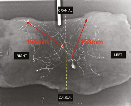
Final X-ray. Red arrows indicate the maximum length from the parasacral artery perforator perforasome to the adjacent perforasome.
Statistical Analysis
Of the 5 cadavers dissected, the total number of perforators in quadrant A was 3, with 2 in quadrant B, 13 in quadrant C, 11 in quadrant D, 6 in quadrant E, and 3 in quadrant F (Supplemental Figure 2, available online at www.aestheticsurgeryjournal.com). There were significantly more perforators in quadrants C and D (respectively, left middle sacral quadrant and right middle sacral quadrant) compared with quadrants A, B, E, and F (Table 3). In fact, there was a significant difference between quadrants C and A (P < 0.02), quadrants C and F (P < 0.02), and quadrants C and B (P < 0.01) in favor of quadrant C. Similarly, there was a significant difference between quadrants D and A (P < 0.04), quadrants D and F (P < 0.04), and quadrants D and B (P < 0.03) in favor of quadrant D. However, there was no significant difference between quadrants C and D (P < 0.69).
Statistical Analysis Results in Terms of Perforant Rate According to the Different Quadrants
| Analysis results/quadrant analyzed (X/Y) | Number (%) quadrant X/number (%) quadrant Y | Z score* or χ 2 test** | P value | Results | ||
|---|---|---|---|---|---|---|
| Observed | Theoretical | |||||
| Quadrant A/B | 3 (60%)/2 (40%) | 2 (40%)/3 (60%) | 0.83** | P < 0.5 | NS | |
| Quadrant A/C | 3 (18.8%)/13 (81.3%) | 8 (50%)/8 (50%) | 2.5* | P < 0.02 | S | |
| Quadrant A/D | 3 (21.4%)/11 (78.6%) | 7 – 50 %/7 – 50 % | 2.13* | P < 0 .04 | S | |
| Quadrant A/E | 3 (33.3%)/6 (66.7%) | 4 (44.4%)/5 (55.6%) | 0,45** | P > 0.9 | NS | |
| Quadrant A/F | 3 (50%)/3 (50 %) | 3 (50%)/3 (50%) | Not calculable | Not calculable | NS | |
| Quadrant B/C | 2 (13. 3%)/13 (86.7) | 7 (46 .7%)/8 (53.3%) | 2.58* | P < 0.01 | S | |
| Quadrant B/D | 2 (15.4%)/11 (84.6%) | 6 (46.2%)/7 (53.8%) | 2.22* | P < 0.03 | S | |
| Quadrant B/E | 2 (25%)/6 (75%) | 4 (50%)/4 (50%) | 2** | P < 0.2 | NS | |
| Quadrant B/F | 2 (40%)/3 (60%) | 3 (60%)/2 (40%) | 0.83** | P < 0.5 | NS | |
| Quadrant C/D | 13 (54.2%)/11 (45.8%) | 12 (50%)/12 (50%) | 0.4* | P < 0.6 | NS | |
| Quadrant C/E | 13 (68.4%)/6 (31.6%) | 9 (47.4%)/10 (52.6%) | 1.83* | P < 0.07 | NS | |
| Quadrant C/F | 13 (81.3%)/3 (18.8%) | 8 (50%)/8 (50%) | 2.5* | P < 0.02 | S | |
| Quadrant D/E | 11 (64.7%)/6 (35.3%) | 9 (52.9%)/8 (47.1%) | 0.97* | P < 0.34 | NS | |
| Quadrant D/F | 11 (78.6%)/3 (21.4%) | 7 (50%)/7 (50%) | 2.13* | P < 0.04 | S | |
| Quadrant E/F | 6 (66.7%)/3 (33.3%) | 5 (55.6%)/4 (44.4%) | 0.45** | P > 0.9 | NS | |
A, left lumbosacral quadrant; B, right lumbosacral quadrant; C, left midsacral quadrant; D, right midsacral quadrant; E, left inferior sacral quadrant; and F, right inferior sacral quadrant. NS, nonsignificant with P > 0.05; S, significant with P < 0.05. *Z Score; **χ2 test.
There were no significant differences between quadrants A, B, E, and F. In fact, quadrants A and B had no significant differences in the number of perforators (P < 0.5), nor were there any between quadrants A and E (P > 0.9), quadrants B and E (P < 0. 2), quadrants B and F (P < 0.5), quadrants C and E (P < 0.07), quadrants D and E (P < 0.34), quadrants E and F (P > 0.9), and quadrants A and F (same number of perforators with n = 3).
Clinical Application
Based on this study, we describe an original surgical procedure in which with utilize PSAPs to achieve gluteal augmentation. This procedure proposes the use of propeller perforator flaps based on PSAPs for gluteal auto-augmentation. Once dissected, the high mobility and large volume allow more optimal buttock filling. These flaps were performed bilaterally during buttock lift in patients with flat buttocks after significant weight loss.
Inclusion criteria were: female patients 18 years of age or more, BMI <30 kg/m2 (recommendations from the French Plastic Surgery Society), having maintained a stable weight for at least 6 months, with skin excess and gluteal ptosis. Exclusion criteria were: patients with chronic disease, active smoking status, hemoglobin <12 g/dL and albumin <3.5 g/dL.
Concerning the preoperative drawings (Figure 10), our findings in the mapping analysis facilitated the color ultrasound or acoustic Doppler location of the perforators, which must be performed preoperatively. Therefore, the long axis of the flap was oriented towards the iliac crests, as suggested by our study. Once harvested and de-epidermized, the flap was placed in each gluteal pocket (Figure 11). Postoperative results are shown in Figure 12.
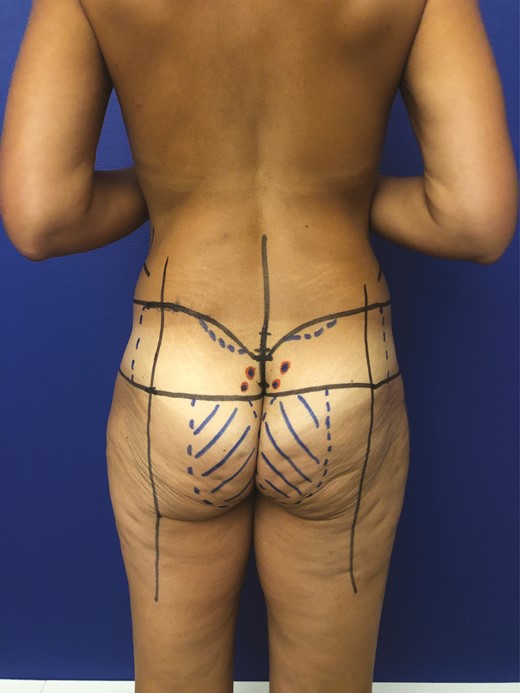
Preoperative drawing for gluteal augmentation with parasacral artery perforator propeller flap for a 50-year-old female patient.
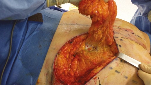
Intraoperative photograph of harvesting and undermining a flap before it was buried in its pocket.
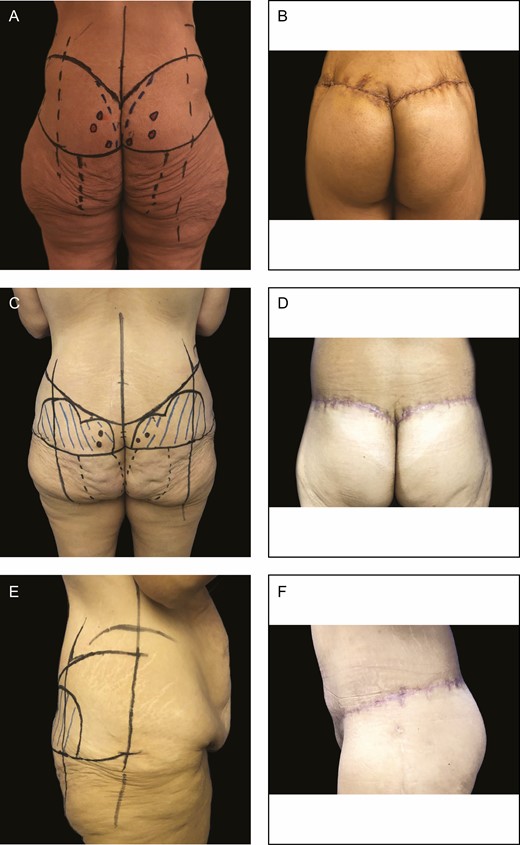
(A) Preoperative and (B) 2-month postoperative results after parasacral artery perforator gluteal augmentation flap for a 46-year-old female patient. (C) Preoperative and (D) 2-month postoperative results after surgery for a 41-year-old female patient. (E, F) Side views of the same 41-year-old female patient 2 months after surgery.
Postoperatively, the patient must remain in prone or lateral position for 3 days. The flaps are monitored daily during these 3 days for discharge, hematoma, and infectious signs. The dressings are redone every 2 days.
No drains are put in place. Patients were monitored for pain and signs of thromboembolic complications twice a day (compression stockings were mandatory until complete healing, about 3 weeks). The patient can walk from the first postoperative day. Sitting and supine position is allowed from the third day. The average hospital stay after operation was 4.4 days.
DISCUSSION
Originally proposed in 2002 by Garrido et al, the PSAP flap was described in a series of 5 patients presenting recurrent pilonidal cyst disease with good results.1 It should not be confused with the SGAP flap as suggested by Koshima et al.9 Perforator flaps are an effective procedure, and have proved useful for covering and reconstructing a variety of sites with integumentary defects. Due to the advent of acoustic and color Doppler ultrasound, their reliability has increased, making it possible to safely identify a given perforator from a source artery and to vascularize a cutaneous, fasciocutaneous, or adipose flap of interest. To date, the literature on these perforators has remained rather sparse. For many indications, pedicled perforator flaps have simplified skin defect management and reduced the duration of procedures.6 For skin defects located close to the sacrococcygeal region, such as pressure sores or pilonidal cysts, the PSAP flap appears to be an interesting procedure due to the versatility of the flap design provides a better match to the defect, and to the increased arc of rotation compared with the conventional rhomboid or Limberg flap.1,3 For sacral pressure sores, the main alternatives are the SGAP or the gluteus maximus muscle flap but with less modularity. However, the gluteus maximus muscle flap is more morbid and unattractive, especially in non-neurologic patients,10 as a rotational flap,11 an island flap,12 or as a V-Y advancement flap.13-15
We have proposed that use of PSAP flap may not be confined to reconstructive surgery but could find a reliable place in aesthetic indications such as gluteal augmentation because it has a significant rotational arc despite its large size. The PSAP mapping and perforasome results from this study highlight this reliability. Mapping provides significant information about PSAPs. First, they are numerous, an average of 8 per sacral area. Second, these PSAPs are of good caliber, >0.5 mm. Third, all PSAPs are located in the sacral area with high density near the midline, about 7 cm below a horizontal line passing through the iliac crests. We also highlighted that the majority of these perforators emerge from sacral foramina. Moreover, according to the statistical analysis, perforators are mostly found in the midsacral regions (quadrants C and D in Supplemental Figure 2), which is consistent with the results of the heat map (Figure 4). Therefore, we recommend focusing Doppler detection in this zone.
This information on perforator location is essential because it saves precious time during the preoperative detection of PSAPs. We recommend acoustic Doppler or colorimetric Doppler ultrasound, which we consider more sensitive and specific, over angioscan16 or regular Doppler ultrasound17,18 to assess preoperative perforators.
Knowledge of the perforasome is also critical because it helps the surgeon to design the flap, ie, knowing which axis and maximum size can be harvested while remaining well-perfused by the chosen perforator(s). Perforasome analysis showed that the perfusion axis was not precisely perpendicular to the midline as described by Saint-Cyr et al for the lumbar and dorsal perforators,6 but rather runs diagonally towards the iliac crests, following the dominant connecting vessels that preferentially connect the parasacral and lumbar network.
Concerning the maximum dimensions that could be removed, cutaneous perfusion of the contrast medium at 130 mmHg could be observed up to an average of 15 cm from the injected perforator. In addition, we assume that it is possible to add to this length random vascularization of the dermal plexus, which is not visible radiologically. Moreover, Venus and Titley performed a 23-cm PSAP flap.19 Therefore, a potential length of 20 cm could be used for flap harvesting, while respecting a long diagonal axis upwards and downwards. This was clinically confirmed for the PSAP flap we used for gluteal augmentation, which was more than 20 cm long (Figure 11). Likewise, Lin et al used PSAPs for sacral coverage of a pressure sore with essential dimensions of almost 200 cm2.2 In comparison, SGAP flaps of a similar size of up to 140 cm2 close to the PSAP area can be harvested, but with a rotation point away from the midline.20
De-epidermization of the gluteal flaps, essential for gluteal augmentation, makes clinical monitoring difficult due to the absence of a skin paddle. Therefore, total or partial failure would result either in local acute complications (cytosteatonecrosis, seroma, infection, etc) or significant volume reduction of the flap. None of these complications occurred in the 3 cases presented here. A study is currently being conducted to investigate these 2 parameters for this new gluteal augmentation technique based on the use of a PSAP propeller flap.
The relevance of gluteal flaps for buttock augmentation according to the classic technique of Lelouarn and Pascal flaps21 is controversial. In fact, the literature reports more complications when flaps are used (42.5%) than when they are not used (19.5%),22 and the postoperative results are sometimes disappointing, mainly due to an unadapted volume distribution. If the marking in our flaps is quite similar, the dissection and undermining are completely different.
Finally, one of the main strengths of this study is the description, for the first time in our review of the literature, of these flaps and this technique. One of the major limitations of this study is the unavailability, for the moment, of long-term follow up of these patients and in particular the results on the shape of the flaps after several years. In the long term, we have observed in our series a correct holding of the flaps (maximum follow up, 2 years). As in the case of the Lelouarn and Pascale flaps, a certain level of crushing is possible in the longer term, and we will monitor this parameter in our patients. The advantage in the buttocks is that the perforators are very numerous and sparse, so it seems possible to model the flaps with great versatility and modularity. Because the flaps are well vascularized, and our results suggest that the sacral skin region has a more robust blood supply than previously thought, we expect sustained volume maintenance. In addition, the flaps are placed without tension because they are mobile, which allows them to be maintained over time. Obviously, each patient is different and particular constraints could emerge on a case-by-case basis. We will also monitor this parameter closely in our patients. Finally, we did not investigate the effects of the lordotic curve on buttock projection postoperatively in our study, although this might have been relevant.
CONCLUSIONS
We confirmed that PSAPs are anatomically different from SGAPs and that they enable harvesting of large pedicled flaps based on parasacral perforators which are useful in sacral or buttock reconstruction and in aesthetic surgery. There is an average of 8 of the largest perforators per sacral region, clustered in an area of high perforator density near the midline, about 7 cm below a horizontal line that passes through the iliac crests. Once located, the design of the corresponding flap should be traced with a central axis oriented towards the homolateral iliac crests to increase their reliability.
Acknowledgments
The authors thank Dr Olivier Mericq for his help with the statistical analysis and Dr Pierre Marek for his help with the imaging study. Drs Claro and Lupon made an equal contribution to this work as co-first authors.
Disclosures
The authors declared no potential conflicts of interest with respect to the research, authorship, and publication of this article.
Funding
The authors received no financial support for the research, authorship, and publication of this article.

